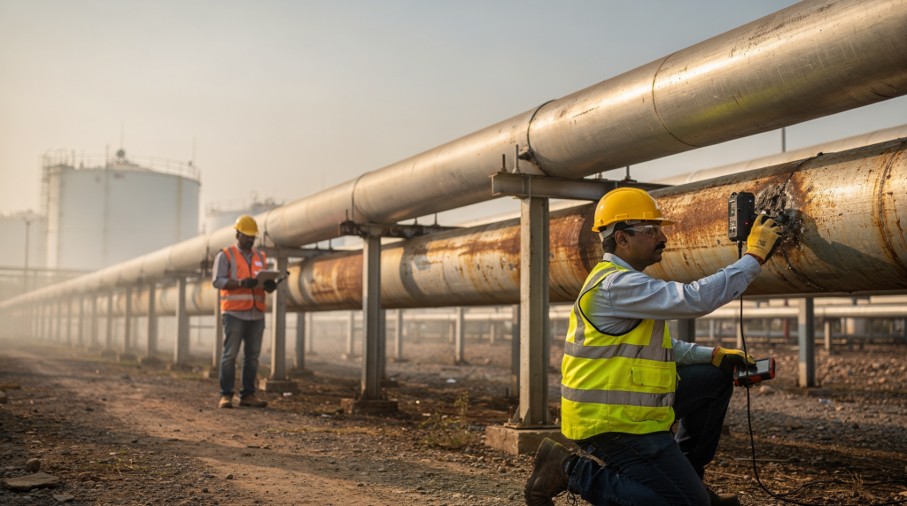
Corrosion in industrial utility pipelines rarely announces itself. It starts quietly — a patch of coating damage, a few microns of wall loss, a pit that deepens month by month — and then one day it becomes a leak, a pressure drop, or an unplanned shutdown that ripples through the entire system. In Indian residential townships and industrial campuses, where water, gas, and sewer lines run through variable soil, coastal humidity, and mixed-use corridors, the cost of missing that early signal is measured not just in repair bills but in disrupted supply, safety risks, and regulatory headaches.
Choosing the right detection method means asking the right questions: are we looking for a general thinning trend, a localized pit, coating failure, or active corrosion happening right now? The answer almost always involves layering several techniques — continuous monitoring for early warning, periodic non‑destructive testing for confirmation, and inline inspection or shutdown surveys when a full integrity picture is needed. This article walks through the methods that work in practice, with an eye on the utility networks that serve Indian residential and industrial projects.
Why corrosion detection matters in utility networks
Corrosion is not a maintenance inconvenience — it is a threat to safety, service continuity, compliance, and the total cost of ownership. In water, gas, sewage, and process utility lines, corrosion can create problems that stay hidden until they become expensive:
- wall loss that progresses for years without a single visible drop of leakage
- localized pits that eat through the pipe wall far faster than uniform corrosion ever would
- scale and deposits that mask the true condition of the metal underneath
- under‑deposit corrosion and microbiologically influenced corrosion that thrive in stagnant, wet environments
- coating defects that let moisture, chlorides, or soil chemicals attack the steel
- repair costs that multiply when damage is discovered only after a failure
In the Indian context, these risks are amplified where pipelines run through humid coastal zones, saline groundwater, mixed utility corridors with stray currents, or areas with unpredictable water chemistry. For a township or industrial campus, a single missed defect in a buried gas line or a main water header can mean days of supply disruption, emergency excavation, and loss of resident confidence. The economics are straightforward: routine inspection is almost always cheaper than emergency response.
How corrosion is detected in practice
A sound corrosion management program never bets on one technique alone. It combines methods that answer different questions:
- Is corrosion happening right now?
- How fast is metal being lost?
- Where exactly is the damage located?
- How severe is it — shallow general thinning or deep pitting?
- Is the protective coating and cathodic protection system still doing its job?
The methods described below are the workhorses of industrial and large‑scale residential utility networks. Each has its place, and the skill lies in matching the method to the specific pipe material, fluid, access, and operating conditions.
1. Ultrasonic thickness testing
Ultrasonic testing sends high‑frequency sound waves through the pipe wall and measures the time it takes for the echo to return. That time directly translates into remaining wall thickness. It is one of the most widely used techniques for spotting corrosion, erosion, and general thinning long before a leak develops.
Best use cases
- spot checks on accessible pipe sections — above‑ground headers, valve stations, pipe racks
- verification after a suspected corrosion event or unusual pressure drop
- baseline thickness surveys and repeat measurements to track loss rates
- gas risers, water mains at building entry points, and exposed utility headers in residential complexes
Strengths
- completely non‑destructive
- fast and relatively low‑cost per measurement point
- delivers direct thickness data, not just an indirect indication
- excellent for trending — comparing readings taken six months or a year apart
Limits
- requires clean, accessible pipe surface; coatings, scale, or heavy rust must be removed at the test point
- measures only the spots you choose — a sparse grid can miss isolated pits
- operator skill matters: poor coupling or surface preparation can give misleading readings
- does not work well on pipes with internal linings unless the lining is accounted for
Practical tip
Treat ultrasonic readings as a trend tool, not a one‑time pass/fail number. In a residential gas network, for example, a 0.2 mm wall loss over two years at a road crossing is far more informative than a single thickness value. Always mark the exact test locations so the next technician measures the same spots.
2. Inline inspection with smart pigs
Inline inspection (ILI) uses tools — often called smart pigs — that travel inside the pipeline, propelled by the product flow. They carry sensors that detect metal loss, cracks, deformations, and other anomalies. Depending on the technology, they may use magnetic flux leakage, ultrasonic transducers, or a combination to map defects along kilometres of pipe in a single run.
Best use cases
- long transmission or distribution lines that feed an industrial estate or a large township
- buried pipelines where external access is limited or excavation is disruptive
- gas and liquid systems designed with pig launchers and receivers
- network‑wide integrity assessments where you need a complete defect inventory
Strengths
- covers long distances in one operation
- provides both the location and the dimensions of defects
- indispensable for buried assets that cannot be inspected externally
- often the best method for mapping internal corrosion in gas and water lines
Limits
- the pipeline must be “piggable” — consistent diameter, gentle bends, no protruding valves or tees that block the tool
- launch and receiver facilities must be built into the design; retrofitting them is expensive
- not suitable for networks with many branch connections, small diameters, or tight geometry
- operationally complex and can be costly, especially for short runs
Practical tip
If a line was not designed for pigging, do not assume you can retrofit it later. During the design stage of a township gas network, insist on piggable mains and dedicated launcher/receiver stations at the entry and exit points. The upfront cost is negligible compared to the cost of a future emergency dig.
3. Corrosion coupons
Corrosion coupons are small, pre‑weighed metal samples inserted into the pipeline environment, usually in a retractable holder. They are left in place for a known period — weeks or months — then removed, cleaned, and weighed. The weight loss gives a direct measurement of the corrosion rate, and visual inspection often reveals the type of attack: uniform, pitting, or galvanic.
Best use cases
- water distribution systems in residential complexes
- process and utility lines where fluid chemistry is monitored
- checking the performance of corrosion inhibitors
- comparative monitoring at multiple points — entry, mid‑zone, and dead ends
Strengths
- simple, low‑cost, and easy to understand
- provides direct exposure data under actual operating conditions
- helps confirm whether chemical treatment is working
Limits
- not real‑time; you only get data when the coupon is pulled
- measures conditions only at the installation point
- retrieval requires a planned intervention
- may not reflect localized damage elsewhere in the system
Practical tip
Place coupons where the risk is highest — low‑flow zones, dead legs, downstream of chemical injection points, and areas with known water quality variations. Installing them only at easily accessible locations gives a false sense of security. In a township water network, a coupon at the farthest end of a distribution loop often tells a very different story than one near the pump house.
4. Electrical resistance probes
Electrical resistance (ER) probes measure metal loss by tracking the increase in electrical resistance as the probe element corrodes. Since the resistance rises as the cross‑section decreases, the instrument can calculate a corrosion rate in real time or near real time.
Best use cases
- continuous monitoring in systems where corrosion rate may change quickly
- inhibitor control programs — you can see within hours whether a dosage adjustment is working
- water, gas, and process utility lines where access for manual checks is difficult
Strengths
- real‑time or near‑real‑time data
- excellent for trend tracking and early warning
- can be integrated into remote monitoring systems
Limits
- does not show the condition of the pipe itself — only the probe element
- probe represents one environment; if conditions vary along the line, one probe is not enough
- sensor placement is critical — a probe in a high‑flow area may not reflect what happens in a stagnant section
Practical tip
Use ER probes where corrosion risk is variable, such as locations with moisture ingress, oxygen entry, or periodic chemical upsets. In a gas distribution network serving a residential colony, an ER probe at a low point where condensate collects can give early warning of internal corrosion that would otherwise go unnoticed.
5. Linear polarization resistance and electrochemical methods
Linear polarization resistance (LPR) and related electrochemical techniques estimate the corrosion rate by applying a small electrical perturbation to the metal and measuring the resulting current. The polarization resistance is inversely proportional to the corrosion rate. These methods are widely used for active corrosion monitoring in aqueous systems.
Best use cases
- water treatment loops and cooling circuits
- utility water headers where chemistry is controlled
- systems where corrosion rate must be tracked closely to adjust chemical dosing
Strengths
- good for active corrosion monitoring
- can provide results quickly — often within minutes
- useful for fine‑tuning inhibitor and biocide programs
Limits
- requires a conductive electrolyte; not suitable for dry gas lines
- interpretation needs technical skill — the measured rate is an instantaneous value that can fluctuate
- electrode fouling or coating can affect accuracy
Practical tip
Electrochemical sensors work best in systems where water chemistry is stable and measurable. In a township’s central water treatment plant, LPR probes on the filtered water header can help the operations team adjust anti‑scalant and corrosion inhibitor doses before the water enters the distribution network.
6. Magnetic flux leakage and electromagnetic methods
Magnetic flux leakage (MFL) uses powerful magnets to saturate the pipe wall with a magnetic field. Where metal is missing — due to corrosion, pitting, or erosion — the field “leaks” out, and sensors detect the disturbance. MFL is a core technology in many smart pigs and external scanning tools.
Best use cases
- ferromagnetic steel pipelines — carbon steel and low‑alloy steel
- buried or otherwise inaccessible lines
- broad defect screening over long distances
Strengths
- good coverage; can scan the entire circumference in one pass
- effective for detecting general metal loss and many types of pitting
- widely used and well‑understood in the pipeline industry
Limits
- not suitable for non‑magnetic materials like stainless steel or some alloys
- crack detection is limited; other techniques may be needed for crack‑like defects
- interpretation depends on calibration, tool speed, and pipe geometry
7. Acoustic emission monitoring
Acoustic emission (AE) listens for the stress waves generated when cracks grow, corrosion products crack, or other active damage processes occur. It does not measure wall thickness — it detects the energy released by ongoing degradation.
Best use cases
- active crack growth monitoring in critical sections
- high‑consequence assets where a sudden failure would be catastrophic
- condition‑based monitoring of sections under cyclic stress or pressure fluctuations
Strengths
- can indicate that damage is happening right now, not just that it exists
- useful for early warning in systems that are difficult to inspect internally
- works well as part of a continuous monitoring strategy
Limits
- background noise — from pumps, traffic, or flow — can mask signals
- interpretation is complex and requires experience
- not a direct thickness measurement; it complements, not replaces, other methods
Practical tip
Use acoustic emission where the goal is to catch active damage before it becomes a leak. In a township gas pipeline crossing a highway, AE sensors can alert the operator to stress corrosion cracking activity long before a pressure test would reveal it.
8. Visual inspection and exposed‑pipe assessment
Never underestimate a trained eye. Visual inspection remains a frontline tool because corrosion often leaves surface clues: blistering paint, rust staining, wet patches, pitting, disbonded insulation, or deposits around joints and supports.
Best use cases
- above‑ground utilities — pipe racks, valve stations, meter rooms
- inspection dig‑outs where buried pipes are temporarily exposed
- areas near supports, clamps, wall penetrations, and expansion joints
Strengths
- quick, inexpensive, and requires minimal equipment
- good for finding external signs of trouble that warrant deeper investigation
- helps decide where to apply more sophisticated NDT methods
Limits
- only sees what is exposed; internal corrosion and under‑insulation damage remain hidden
- cannot quantify wall loss
- not reliable as a standalone method for buried or insulated lines
9. Radiography and other advanced NDT methods
Radiography — using X‑rays or gamma rays — produces an image of the pipe wall that reveals thickness variations, weld defects, and internal corrosion. Other advanced methods like phased array ultrasonics and eddy current testing also come into play when detailed defect characterization is needed.
Best use cases
- critical weld areas and heat‑affected zones
- confirmation after other inspections have flagged an anomaly
- difficult‑to‑interpret indications where you need a definitive answer
Limits
- more specialized — requires trained personnel, permits, and safety controls
- usually not a first‑line monitoring tool; used for targeted investigation
- access may be difficult, and radiation safety boundaries must be established
Comparison table: which method fits which problem?
| Method | Best for | Strength | Main limitation |
|---|---|---|---|
| Ultrasonic thickness testing | Wall loss measurement | Direct thickness data | Point‑based, needs access |
| Smart pigging / ILI | Long buried pipelines | Wide coverage and defect mapping | Requires piggable line |
| Corrosion coupons | Corrosion rate confirmation | Simple and low‑cost | Not real‑time |
| ER probes | Ongoing corrosion rate tracking | Real‑time trend data | Measures one location only |
| LPR / electrochemical monitoring | Water‑based systems | Fast rate estimation | Needs electrolyte |
| MFL | Metal loss detection | Good broad coverage | Crack detection limits |
| Acoustic emission | Active damage warning | Early event detection | Interpretation complexity |
| Visual inspection | Surface clues | Fast screening | Limited to exposed areas |
A practical corrosion detection program for industrial utility networks
The most effective programs follow a four‑step rhythm: baseline, risk mapping, method matching, and trending. Here is how that looks in practice.
Step 1: Set a baseline
Before the system enters full service — or as early as possible — record the fundamentals:
- installed pipe material and grade
- coating type and application date
- design pressure and operating temperature
- water or fluid chemistry (pH, chlorides, dissolved oxygen, conductivity)
- initial ultrasonic thickness readings at agreed locations
- known high‑risk locations: road crossings, creek beds, areas with poor drainage
Without a baseline, later readings are just numbers with no context. A thickness of 5.2 mm means nothing unless you know it started at 6.0 mm three years ago.
Step 2: Identify high‑risk zones
Corrosion does not spread evenly. Focus your inspection resources on:
- low points where water or condensate collects
- dead legs and stagnant sections that rarely see flow
- areas near supports, clamps, and pipe shoes where coating is often damaged
- coating transitions — buried‑to‑above‑ground interfaces
- buried sections in aggressive soil (high salinity, low resistivity)
- coastal or high‑humidity locations with airborne chlorides
- places with poor drainage, insulation damage, or previous repair history
Step 3: Use the right method for the right question
- Use ultrasonic testing for spot thickness checks and trending.
- Use coupons or ER probes for corrosion rate monitoring.
- Use smart pigging for buried line surveys when the line is piggable.
- Use visual inspection for external clues on above‑ground sections.
- Use electrochemical monitoring in water‑based systems where chemistry is controlled.
- Use acoustic emission when active damage is suspected and you need early warning.
Step 4: Trend the data
A single inspection is a snapshot; trends tell the story. Compare:
- thickness loss over time at the same locations
- corrosion rate before and after chemical treatment changes
- defect growth between inline inspections
- sensor data against operating changes — flow rate, temperature, water source switch
Common mistakes to avoid
- relying on visual inspection alone for buried or insulated lines
- placing sensors only where access is easy, not where risk is highest
- treating one thickness reading as a full integrity assessment
- ignoring dead legs and stagnant zones — they often corrode faster than flowing lines
- skipping coating and cathodic protection checks when wall loss is found
- using the same method for every pipeline type without considering material and fluid
- failing to correlate inspection results with operating conditions — a spike in corrosion rate often has a process cause
When to escalate from monitoring to repair
Escalate when you see:
- accelerating wall loss — the rate is increasing, not stable
- recurring leaks at the same section
- deep pitting that exceeds 50–70% of original wall thickness
- coating breakdown with active corrosion underneath
- abnormal readings from multiple independent methods
- evidence that corrosion inhibitors are no longer effective
Once defect growth is confirmed, the response may include repair clamps, section replacement, internal relining, coating renewal, inhibitor adjustment, or a review of the cathodic protection system. The key is to act before the defect becomes a failure.
Checklist for site teams
- Do we know which pipes are piggable and which are not?
- Do we have baseline thickness data for all critical lines?
- Are coupons or probes installed in representative high‑risk locations, not just convenient ones?
- Have high‑risk zones been mapped and marked on site drawings?
- Is the inspection interval based on actual risk assessment, not a generic calendar schedule?
- Are thickness readings trended over time, and are the trends reviewed regularly?
- Has coating condition been checked along with wall loss measurements?
- Are chemistry, flow, and operating changes linked to corrosion data so that cause and effect can be traced?
Corrosion detection strategy by pipeline type
| Pipeline type | Recommended approach |
|---|---|
| Buried steel gas line | Smart pigging (if piggable), ER probes at critical points, external coating survey, targeted ultrasonic testing at road crossings |
| Water utility header | Ultrasonic thickness trending, corrosion coupons, LPR probes, regular visual inspection of exposed sections |
| Sewage or effluent line | Ultrasonic testing at accessible points, visual checks during maintenance windows, review of material selection for corrosion resistance |
| Process utility line | Ultrasonic testing, ER probes, electrochemical monitoring where applicable |
| Long buried industrial corridor | Inline inspection for full‑length assessment, supplemented by high‑risk point monitoring with probes and periodic UT |
Final takeaway
There is no single best corrosion detection method for every industrial utility network. The right answer is always a combination — a layered strategy that matches techniques to the pipe material, service conditions, and access constraints. For most industrial and township utility systems, the strongest program blends real‑time monitoring (probes, sensors), periodic thickness measurement (ultrasonic testing), and occasional inline inspection for buried assets. That combination catches corrosion early, reduces the risk of emergency repairs, and gives asset owners a clear, defensible picture of remaining pipeline life. In Indian residential projects, where utility reliability directly affects daily life, this approach is not just good engineering — it is a promise of uninterrupted service.
FAQ
What is the most common method for detecting pipeline corrosion?
Ultrasonic thickness testing and inline inspection are the most common because they directly assess wall loss and defect location. In residential gas networks, ultrasonic spot checks on risers and entry points are routine, while inline inspection is reserved for the larger transmission mains that feed the township.
Can corrosion be detected before a leak happens?
Absolutely. Coupons, ER probes, LPR sensors, ultrasonic testing, and inline inspection all detect corrosion long before a through‑wall leak occurs. The key is to combine methods so that you catch both general thinning and localized pitting. A well‑monitored water main in a housing complex can show a gradual wall loss trend years before any water appears on the surface.
Is smart pigging suitable for every pipeline?
No. Smart pigging requires a pipeline designed with consistent diameter, gentle bends, and dedicated launcher/receiver facilities. Most intra‑township distribution lines are not piggable due to smaller diameters and numerous branch connections. For those, external methods like ultrasonic testing and probe monitoring are the practical choice.
Are corrosion coupons enough on their own?
No. Coupons give a reliable average corrosion rate at one point, but they are not real‑time and cannot detect isolated pitting elsewhere. They work best as part of a broader program that includes thickness measurements and, where possible, continuous monitoring.
Which method is best for buried pipelines?
Inline inspection is often the strongest option for buried lines because it covers the entire length and finds defects regardless of depth. When pigging is not possible, a combination of external coating surveys, targeted ultrasonic testing at excavated bellholes, and ER probes at accessible locations provides a practical alternative.
How often should corrosion be checked?
The interval depends on operating risk, pipe material, environment, and previous findings. A buried gas line in corrosive soil may need annual inline inspection or probe monitoring, while a stable above‑ground water header in a controlled environment might be checked every two to three years. The rule is simple: high‑risk lines need more frequent monitoring; low‑risk, stable systems can be inspected less often — but never ignored.